Implementing Cisco Enterprise Advanced Routing and Services (ENARSI)
Exam Details
Exam Code
:300-410
Exam Name
:Implementing Cisco Enterprise Advanced Routing and Services (ENARSI)
Certification
:CCNP Enterprise
Vendor
:Cisco
Total Questions
:925 Q&As
Last Updated
:Apr 17, 2025
Cisco CCNP Enterprise 300-410 Questions & Answers
Question 591:
You have been alerted that TCP traffic leaving an interface has been reduced to near zero, while UDP traffic is steadily increasing at the same time.
What is this behavior called and what causes it?
A. jitter, caused by lack of QoS
B. latency, caused by the MTU
C. starvation, caused improper configuration of QoS queues
D. windowing, caused by network congestion
Correct Answer: C
This behavior is called starvation and is caused by improper configuration of QoS queues. When TCP and UDP flows are assigned to the same QoS queue, they compete with one another. This is not a fair competition because the TCP
packets will react to packet drops by throttling back TCP traffic, while UDP packets are oblivious to drops and will take up the slack created by the diminishing TCP traffic. The results from mixing UDP and TCP traffic in the same queue are:
Starvation
Latency
Lower throughput
While it is true that jitter can be caused by a lack of QoS, jitter is not what is being described in the scenario. Jitter is the variation in latency as measured in the variability over time of the packet latency across a network. This phenomenon
seriously impacts time-sensitive traffic, such as VoIP, and can be prevented by placing this traffic in a high-priority QoS queue.
While latency can be caused by the maximum transmission unit (MTU) in the network, this is not a case of latency, although latency may be one of the perceived effects of starvation. Latency is the delay in reception of packets. The MTU is
the largest packet size allowed to be transmitted, and an MTU that is set too large can result in latency.
While windowing can be caused by network congestion, this is not a case of windowing. This is a technique used to adjust the number of packets that can acknowledged at once by a receiving computer in a transmission. In times of
congestion the window, or number of packets that can be acknowledged at a time, will be small. Later, when congestion goes down, the window size can be increased.
Objective:
Network Principles
Sub-Objective:
Describe UDP operations
References:
Design Guide > Service Provider Quality of Service > CE Guidelines for Collapsing Enterprise Classes > Mixing TCP with UDP
Question 592:
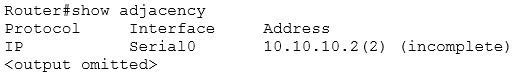
Examine the following output.
What possible reason(s) can cause the state of the first entry in the adjacency table? (Choose all that apply.)
A. the interface is a multipoint interface
B. the clear ip arp command was executed
C. the Layer 3 information is unknown
D. the clear adjacency command was executed
Correct Answer: BD
If either the clear ip arp or the clear adjacency commands were issued, the entry would temporarily be listed as incomplete in the adjacency table. The adjacency table is used by Cisco Express Forwarding (CEF) to maintain Layer 2 information about the next hop to remote networks. In CEF, an adjacency refers to a control structure that holds Layer 2 information for an IP address on a particular interface. When that information is not available the entry will be listed as incomplete, as shown in the example.
Layer 2 information normally comes from the ARP process. Therefore, if the ARP table is cleared with the clear ip arp command, the Layer 2 information will be temporarily unavailable until the ARP process re-learns it the next time a frame must be sent to that hop. Moreover, if the adjacency table is emptied with the clear adjacency command, the entry must be created again. This will also result in the entry being marked incomplete for a short period of time until the ARP table can be consulted and the Layer 2 information re- added.
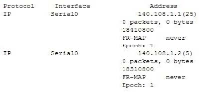
The interface in the scenario is not a multipoint interface. A multipoint interface would include entries for multiple next hops, since a multipoint interface connects to multiple Layer 3 destinations. An example of this is shown below in sample output from a Frame Relay interface:
The layer 3 information of the next hop is present in the entry in the scenario example. It is 10.10.10.2.
Objective:
Network Principles
Sub-Objective:
Identify Cisco Express Forwarding concepts
References:
Home > Support > Technology support > IP > IP switching > Troubleshoot and alerts > Troubleshooting Technotes > Troubleshooting Incomplete Adjacencies with CEF
Question 593:
Which of the following statements represent characteristics of an automatic 6to4 tunnel through an IPv4 network? (Choose all that apply.)
A. There is a NAT-PT router on either end of the tunnel.
B. There is a dual stack router on either end of the tunnel.
C. Each 6to4 site will have a /48 prefix.
D. Each 6to4 site will have a /16 prefix.
E. The IPv4 addresses of the edge routers are part of the site prefix.
F. The IPv6 addresses of the sending and receiving IPv6 hosts are part of the site prefix.
Correct Answer: BCE
When implementing an automatic 6to4 tunnel, each IPv6 site receives a 48-bit prefix. The hexadecimal equivalent of the IPv4 address of the edge router is appended to 0x2002 and followed with the prefix to identify each end of the tunnel.
Each end of the tunnel must be a dual stack router, which is one that can route both IPv4 and IPv6 traffic. For example, if the edge router's IPv4 address were 192.168.99.1, the hexadecimal equivalent of the address (c0a8:6301) would be
inserted between 0X2002 and the /48 prefix, resulting in a packet with the IPv6 address 2002:c0a8:6301::/48 to arrive at the tunnel endpoint address.
A Network Address Translation - Port Translation (NAT-PT) router performs translation from IPv4 to IPv6. It is not used in a 6to4 tunnel.
Each site does not have a /16 prefix with a 6to4 tunnel. Rather, each site has a /48 prefix.
The IPv6 address of each IPv6 host is not part of the site prefix. These addresses are retained within the IPv6 portion of the header, and will be read after the frame reaches the end of the tunnel for eventual IPv6 routing on the far end.
Which of the following IPv6/IPv4 interoperability techniques routes both IP versions simultaneously?
A. NAT-PT
B. Dual stack
C. 6to4 tunnels
D. Teredo
Correct Answer: B
When the routers in the network are capable of routing both IPv6 and IPv4 traffic, it is referred to as dual stack. The dual stack routers simply recognize the version a frame is using and react accordingly to each frame.
Network Address Translation- Port Translation (NAT-PT) is a service that runs on a router or server that converts IPv4 traffic to IPv6, and vice versa. This eliminates the need for the routers or clients to be dual stack- capable. When only one
router exists between the IPv4 and the IPv6 networks, this will be the only option, since all other methods listed require a dual stack capable device on each end of the tunnel. The IPv6 to IPv4 mapping can be obtained by the host from a DNS
server, or the mapping can be statically defined on the NAT device.
6to4 tunnels can be created between dual stack routers or between a dual stack router and a dual stack client. In either case, each tunnel endpoint will have both an IPv6 and an IPv4 address. When traffic needs to cross an area where IPv6
is not supported, the tunnel can be used to transport the IPv6 packet within an IPv4 frame. When the frame reaches the end of the tunnel, the IPv4 header is removed and the IPv6 frame is further routed based on its IPv6 address.
Teredo is an alternate tunneling mechanism that encapsulates the IPv6 frame in an IPv4 UDP packet. It has the added benefit of traversing a NAT device that is converting private IP addresses to public IP addresses. 6to4 tunnels cannot
traverse NAT devices by converting private IP addresses to public IP addresses.
Objective:
Network Principles
Sub-Objective:
Recognize proposed changes to the network
References:
Cisco > Home > Products and Services > Cisco IOS and NX-OS Software > Cisco IOS Technologies > IPV6 > Product Literature > White Papers > Federal Agencies and the Transition to IPv6 Cisco > Cisco IOS IPv6 Configuration Guide,
Release 15.2MT
Question 595:
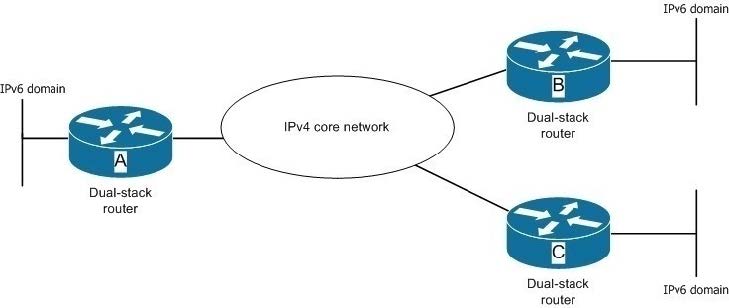
An enterprise has implemented an IPv4 addressing scheme on the servers of its core network. To effectively handle the increasing user requests to the server, the enterprise has plans to implement three new subnets with IPv6 addressing in its existing IPv4 network. The network administrator has set up dual-stack routers on the boundary of these subnets, as shown in the network diagram.
You need to ensure interoperability between IPv4 and IPv6 hosts such that routers A, B, and C can dynamically determine the destination of an IPv6 packet. In addition, global unicast addresses should be supported on all hosts in the three IPv6 subnets.
Which of the following tunneling method can be used between the three routers? (Choose two.)
A. GRE tunnel
B. Automatic 6-to-4 tunnel
C. ISATAP tunnel
D. Manually-configured tunnel
Correct Answer: BC
You can use either automatic 6-to-4 tunnel or an Intra-site Automatic Tunnel Addressing Protocol (ISATAP) tunnel. Both of these tunneling methods are point-to-multipoint tunneling methods. This means that a single router (the point) can
send IPv6 packets to different IPv6 routers (multipoints), depending on the destination address. When a router receives an IPv6 packet from an IPv6 host, it encapsulates the IPv6 packet in an IPv4 packet, which is then sent through the IPv4
core network. When the IPv4 packet is received at the destination router, the IPv6 address is extracted from the IPv4 packet and then forwarded to the intended IPv6 host.
Automatic 6-to-4 tunnels are created automatically by two IPv6 routers separated by an IPv4 network. These tunnels consider the IPv4 network as a virtual non-broadcast multi-access (NBMA) link. The tunnel is formed for every IPv6 packet
that travels from one IPv6 border router to another IPv6 border router. IPv4 and IPv6 must be supported at both the border routers.
In automatic 6-to-4 tunneling, addresses belonging to the 2002::/16 prefix are used. In such IPv6 addresses, the 32-bit IPv4 address of each edge router is embedded into its IPv6 address increasing the length of the prefix to 48 (16 + 32). In
automatic 6-to-4 tunnel, the IPv4 address of the router is embedded into the second the third quartet of the IPv6 address of the router.
ISATAP is also an automatic tunneling mechanism that uses an underlying IPv4 network as a NBMA link for IPv6 networks. However, it is most suitable for exchanging packets within an IPv6 network instead of exchanging packets between
two IPv6 networks. With ISATAP tunnels, IPv6 dual-stack routers connected through the same IPv4 network can communicate with one another.
ISATAP works with unicast IPv6 addresses that are identified by a 64-bit prefix. The lowermost 64 bits are used to identify the interface of the router and are in modified EUI-64 format. The 0:5eFe value exists in the first 32 bits of the interface
identifier. This value indicates that the IPv6 address is an ISATAP address. The remaining 32 bits contain the hexadecimal value of the IPv4 address; that is, the seventh and the eighth quartets in the IPv6 contain the IPv4 address.
You should not use a GRE tunnel or a manually configured tunnel between the three routers. These two tunneling methods provide static point-to-point tunnel between two IPv6 routers through an IPv4 network. Both these tunneling methods
assume a virtual point-to-point link.
Objective:
Network Principles
Sub-Objective:
Recognize proposed changes to the network
References:
Cisco IPv6 Implementation Guide; Implementing Tunneling for IPv6
Question 596:
Which dialer interface command sets the maximum size of IP packets to 1492?
A. router(config-if)# mtu 1492
B. router(config-if)# ip ppp 1492
C. router(config-if)# ip 1492
D. router(config-if)# ip mtu 1492
Correct Answer: D
The correct interface command to set the maximum size of IP packets (maximum transmission unit or MTU size) to 1492 is router(config-if)# ip mtu 1492. This command is required because RFC 2516 states the maximum receive unit (MRU)
must not be negotiated larger than 1492 bytes.
All other answers are invalid commands due to incorrect syntax.
Objective:
Network Principles
Sub-Objective:
Explain TCP operations
References:
Cisco > Cisco IOS IP Application Services Command Reference > idle (firewall farm datagram protocol) through ip slb natpool > ip mtu
Question 597:
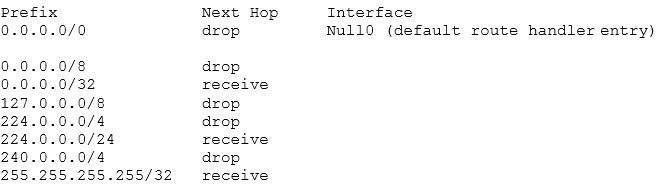
Examine the following FIB table:
Which of the following statements is NOT true?
A. These are the default entries in an FIB table
B. No IP addresses have been configured on this router
C. Multicast routing is enabled
D. The gateway of last resort has not been set
Correct Answer: C
The Forwarding Information Base (FIB) table is created when Cisco Express Forwarding (CEF) is enabled on the router. FIB is a mapping of destination networks and IP addresses to next-hop IP addresses and exit interfaces.
In the scenario, multicast routing has NOT enabled in the router. If it were enabled, the next hop for the 224.0.0.0/4 network would not be listed as drop. A drop means any packets sent to multicast IP addresses will be dropped. If multicast
routing were enabled, the entry for 224.0.0.0 would appear as follows:
Prefix Next Hop Interface
224.0.0.0/4 0.0.0.0
The next hop of 0.0.0.0 means that this traffic will be process switched, and CEF cannot forward the packets.
The table displayed in the scenario contains the default entries in the FIB. These entries will change based on further configuration of the router interfaces and the addition of routes to the routing table through either static routing or through
routing protocols.
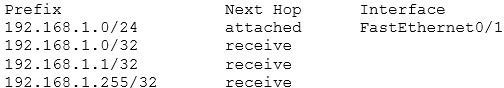
No IP addresses have been configured on the router. Had they been configured, the addresses of the networks to which they were connected would be in the table. For example, if the IP address of the FastEthernet 0/1 interface were set to 192.168.1.1/24, three entries would have been added to the table as follows:
While the first IP address represents the directly attached network of which the interface is a member, the second IP address represents the network ID of the network, the third IP address represents the specific IP address assigned to the
interface, and the last IP address represents the broadcast address of the network.
The gateway of last resort has not been set on the router. If it were set, it would be listed along with an IP address for the next hop and the exit interface. An entry for a gateway of last resort (or default route) would resemble the following:
Prefix Next Hop Interface
0.0.0.0/0 192.168.5.5 FastEthernet 0/0
Objective:
Network Principles
Sub-Objective:
Identify Cisco Express Forwarding concepts
References:
Cisco IOS Switching Services Configuration Guide, Release 12.2 > Cisco Express Forwarding Overview Cisco > Home > Support > Product Support > Routers > Cisco 12000 Series Routers > Troubleshoot and Alerts > Troubleshooting
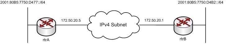
You have implemented an automatic 6-to-4 tunnel between the routers rtrA and rtrB as shown in the following network diagram:
The routers rtrA and rtrB are connected to two IPv6 subnets and are separated by an IPv4 network. You decide to verify whether the tunnel was correctly implemented using the show running-config command. Which of the following commands should exist in the output of the show running-config command on rtrA and rtrB? (Choose all that apply.)
A. interface tunnel
B. tunnel source
C. tunnel destination
D. tunnel mode ipv6ip
E. tunnel mode ipv6ip 6to4
Correct Answer: ABE
The following commands should exist in the output of the show running-config command on rtrA and rtrB: interface tunnel tunnel source
tunnel mode ipv6ip 6to4
The interface tunnel command is used to define a tunnel interface on the router. The tunnel source command allows you to specify the source of the tunnel, which is the router interface that faces the IPv4 network. The tunnel source must be
configured with an IPv4 address. The tunnel mode ipv6ip 6to4 command is used to specify the tunneling mechanism, which in this case is automatic 6-to-4.
The partial output of the show running-config command on rtrA is as follows:
!
interface Tunnel0
no ip address
tunnel mode ipv6ip 6to4
tunnel source 172.50.20.5
ipv6 address 2002:ac32:of06::1/48
!
The partial output of the show running-config command on rtrB is as follows:
!
interface Tunnel0
no ip address
tunnel mode ipv6ip 6to4
tunnel source 172.50.20.1
ipv6 address 2002:ac32:0f06::2/48
!
The tunnel destination command and the tunnel mode ipv6ip commands do not appear in the show running- config output when automatic 6-to-4 tunnels are implemented on rtrA and rtrB. Both of these commands are executed for manually
configured tunnels.
Objective:
Network Principles
Sub-Objective:
Recognize proposed changes to the network
References:
Cisco Press > Articles > Cisco Certification > CCNP > CCNP Self-Study: Advanced IP Addressing Cisco Interface and Hardware Component Configuration Guide > IPv6 Automatic 6to4 Tunnels Cisco > Support > Technology Support > IP >
IP Version 6 (IPV6) > Configure > Configuration Examples and Technotes > IPv6 Tunnel Through an IPv4 Network
Cisco IOS IPv6 Implementation Guide > Implementing Tunneling for IPv6
Question 599:
Which of the following statements are TRUE about manually configured IPV4-to-IP6 tunnels and GRE tunnels? (Choose two.)
A. Manually configured tunnels use the tunnel mode ipv6ip command, while GRE tunnels use the tunnel mode gre ip command.
B. Manually configured tunnels support IPv6 IGPs, while GRE tunnels do not.
C. Manually configured tunnels block IPv6 multicasts, while GRE forwards them.
D. Manually configured tunnels do not support multiple passenger protocols, while GRE tunnels support them.
Correct Answer: AD
The following statements are TRUE about manually configured tunnels and GRE tunnels:
Manually configured tunnels use the tunnel mode ipv6ip command, while GRE tunnels use the tunnel mode gre ip command.
Manually configured tunnels do not support multiple passenger protocols, while GRE tunnels support them.
Manually configured tunnels and Generic Routing Encapsulation (GRE) tunnels are static point-to-point tunneling methods. Both of these tunneling methods provide a permanent link between two IPv6 networks that are separated by an IPv4
backbone. For each link between two IPv6 networks, a separate tunnel needs to be created.
Manually configured tunnels use a particular passenger protocol and do not support multiple passenger protocols at the same time. However, GRE tunnels can simultaneously use various passenger protocols.
It is incorrect to state that manually configured tunnels support IPv6 IGPs, while GRE tunnels do not. GRE tunnels also support IPv6 IGPs, such as OSPF, RIP, and IS-IS.
It is incorrect to state that manually configured tunnels block IPv6 multicasts, while GRE forwards them.
Manually configured tunnels also forward IPv6 multicasts.
Objective:
Network Principles
Sub-Objective:
Recognize proposed changes to the network
References:
Cisco IOS IPv6 Configuration Guide, Release 12.4 > Implementing Tunneling for IPv6 > Configuration Examples for Implementing Tunneling for IPv6 > Example: Configuring Manual IPv6 Tunnels
Question 600:
Your company has implemented IPv6 addresses and routing on every host, server, and router. Recently, your company acquired another company that has an IPv4 addressing scheme for its entire network. The acquired company's network does not have any support for IPv6. You need to devise a method so that the IPv6 hosts in your company can seamlessly communicate with the IPv4 hosts of the acquired company's network. You do not want to install any additional routers, and you want minimum configuration changes on the networks. Which of the following is the best method to allow communication between the IPv4 and IPv6 hosts?
A. Embedding IPv6 packets into IPv4 packets
B. Translating IPv4 addresses to and from IPv6 addresses
C. Configuring IPv6 on the hosts and routers in the IPv4 network
D. ConfiguringIPv4 on the hosts and routers in the IPv6 network
Correct Answer: B
Translating IPv4 addresses to and from IPv6 addresses is the best method to allow communication between the IPv4 and IPv6 hosts. This translation of IPv4 and IPv6 addresses is known as Network Address Translation-Protocol Translation
(NAT-PT). NAT-PT is a technique available for deploying IPv6 and IPv4 addresses in a unified network. With NAT-PT, the network requires fewer modifications and software for the IPv4 and IPv6 hosts. Additionally, it provides easy and quick
interoperability between the IPv4 and IPv6 hosts.
NAT-PT is configured on one of the routers on the border of the IPv4 and IPv6 networks. Whenever an IPv4 packet intended for a host in the IPv6 network is received by the NAT-PT router, the router applies NAT-PT on the packet and
translates all the headers in the IPv4 headers. In addition, it translates the IPv4 source and destination addresses to IPv6 source and destination addresses. The IPv6 packet is then set by the NAT-PT router to the intended IPv6 host. The
NAT-PT router performs the reverse translation when an IPv6 host sends a packet to an IPv4 host.
Embedding IPv6 packets into IPv4 packets is not the best method to allow communication between the IPv4 and IPv6 hosts. When IPv6 packets are embedded inside IPv4 packets, the process is referred to as tunneling. Tunneling is
appropriate when two IPv6 networks are separated by an IPv4 network. When an IPv6 host of one network sends an IPv6 packet destined for a host on the other IPv6 network, an IPv4 tunnel is created between the two IPv6 networks. The
IPv6 packet is then embedded into an IPv4 packet that traverses through the IPv4 tunnel to reach the intended IPv6 host, where the embedded packet is extracted by the recipient. In this scenario, a single IPv6 network is available; hence, a
tunnel cannot be formed.
Configuring IPv6 on the hosts and routers in the IPv4 network, or configuring IPv4 on the hosts and routers in the IPv6 network, are not the best methods to allow communication between the IPv4 and IPv6 hosts. Each of these two methods
is cumbersome and not the most efficient for providing interoperability between IPv4 and IPv6 in this case. Furthermore, the IPv4 hosts on the acquired company's network do not support IPv6 as stated.
Objective:
Network Principles
Sub-Objective:
Recognize proposed changes to the network
References:
Cisco NAT Configuration Guide, Release 15MandT > NAT-PT for IPv6
Nowadays, the certification exams become more and more important and required by more and more enterprises when applying for a job. But how to prepare for the exam effectively? How to prepare for the exam in a short time with less efforts? How to get a ideal result and how to find the most reliable resources? Here on Vcedump.com, you will find all the answers. Vcedump.com provide not only Cisco exam questions, answers and explanations but also complete assistance on your exam preparation and certification application. If you are confused on your 300-410 exam preparations and Cisco certification application, do not hesitate to visit our Vcedump.com to find your solutions here.